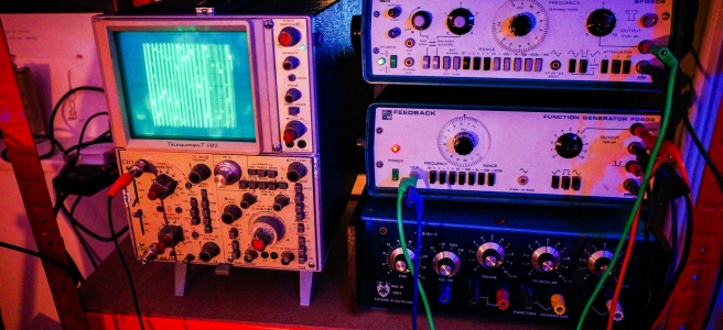
Recently I embarked on an experimentation with old audio test equipment, Specifcally, these devices used in labs and by engineers to diagnose problems with amplifiers, radios, and telephone lines. Err, I think. To be honest, I’m not entirely sure what they were designed for, as I was no good at physics.
Either way, they look cool, and I’ve been interested in exploring some of the possibilities for a while, but didn’t know where to begin. However, I came across this guy called Hainbach on YouTube, who has put together an awesome guide that helped give me the push to dive in. I picked up a few different pieces for cheap on eBay, and began playing about with them to see what I could do. I mostly got a hold of audio signal generators, which are essentially what gives synthesizers their voice. The extent to which you can control them differs from instruments, but I was able to get some amazing sounds out of them.
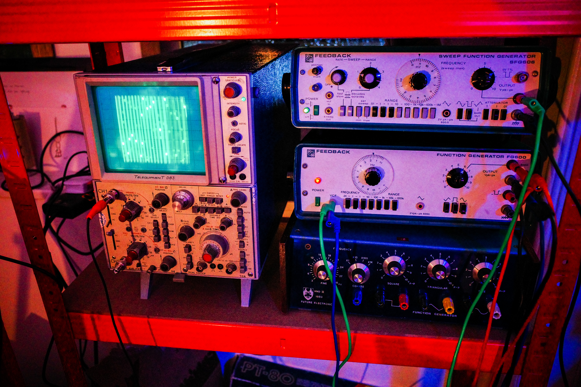
I put together the track below with a single one of these devices, controlled by my Eurorack to some extent. Unlike a lot of my other music, there’s very few effects on here, and very few layers; the sounds of the test equipment stand on their own. Pretty much everything you hear (minus drums) is from the Feedback Function Generator. I love that I can get a really incredible ratchety bass sound out of this, jumping down from nice and melodic to aggressive. Perhaps I’m imagining it, but I haven’t been able to get that kind of usable range from any of my other equipment. Either way, there’s something deeply satisfying about making music with aging bits of technology that were never intended to be used this way - it sparks the creative process in a different way.
At some point I’ll go through and write a bit more about this stuff in detail, but for now, I put together this video with my initial faffing about:
I’m the sort of person who is far more comfortable in dark spaces than I am with bright, overhead lights. I also love how colourful lights look in pictures, so am always on the hunt for different ways to implement LEDs. They also go hand in hand with a sweeeeet looking music setup.
Anyway, I used to have a neon sign in the home studio which gave a real nice ambience, but unfortunately it blew up… so I had to hunt for a replacement. I trialled some 5v RB LED strips on the outside of the case, and it looked pretty cool - but it needed some tweaking.
I came across the Doepfer A-197-3 module which allows you to control LEDs with CV signals from the Eurorack, and it got me thinking. I didn’t want to spend the money or HP on the Doepfer without first figuring out if it would be worth it. It worked with 12v LED strips, so I picked up 5m of them off of eBay, complete with what claimed to be a ‘sound reactive controller’. In theory, it should play along nicely with the audio output from my rig, though to be honest, I wasn’t holding out much hope. These kinds of thing are infamously of questionable quality, and I fully expected to have to pick up the Doepfer module anyway.
However… it actually turned out alright. The modes and sensitivity controls work quite nicely, and despite a few hiccups, putting the strips together was easier than I expected. I ended up lighting the outside of the three main parts of my setup, and it looks pretty great. I put together a video below going into some more detail, and showing them in action. Take a look below if you’re interested.
This isn’t going to be the end of the lighting adventures though. I have a few ideas up my sleeve that I am going to try out over the next wee while, so watch this space (and maybe subscribe to the YouTube).
In my wild youth I used to fling my guitars about on stage with gay abandon - something that I’ve done less as I’ve gotten older. At this point I’m too attached to most of them, and not prepared to risk a terminal injury from another aerial flight into the drumkit at the end of a gig.
To try and remedy this, I picked up an Encore Strat (in a rather fetching hot pink colour) for a measly thirty quid - the plan being that I would upgrade a couple of bits and pieces to make it passable for live use, and deploy it for the higher energy situations where things may end up getting out of hand. Here is the Facebook marketplace picture that sold me on it:
As you can see, it looks pretty great - especially with the matching pink headstock. In person, there were a few things of note:
The body itself was extremely light, and felt like it would literally just smash into smithereens if it took a hard whack in the right place.
Perhaps because of this, it seemed like there was an unusual amount of sustain, with any vibrations or knocks resonating through the body pretty well. Maybe not the best for other guitars, but for a feedback noise monster this should be pretty great.
The pickups and bridge were fine. As were the pots. Pretty bog standard stuff.
The pickup selector switch was genuinely atrocious, and was so loose I couldn’t really tell which setting was which. I’m not sure if that was a problem from the factory, or something that had developed over time - but either way it wasn’t good.
The machine heads were really crappy and plastic - and it seemed like they didn’t hold the strings in tune especially well.
The fretboard was generally fine, and the action not too bad at all - though the neck lacked a bit of polish - and it felt fairly low quality overall as a result.
The frets badly needed a polish.
Since it was second hand, the pickguard was a bit grubby.
One of the strap buttons were missing.
There was no shielding of the cavity - just a portion of the pickguard.
Since the plan was to actually play this guitar live - rather than to just smash it up for the hell of it, I wanted it to be at least semi respectable, and took the opportunity to modify some of the poorer quality elements to bring it up to scratch.
I have no idea what I am doing.
I toyed with the idea of going the full hog: replacing the shoddy pickup selector switch, installing higher quality pots, etc, but in the end I stripped the upgrades down to the most ‘essential’ elements that I was going to be using.
I removed both of the tone knobs, and shifted the volume knob down so it was out of the way. This mod is a slightly more exaggerated version of a mod that I do to all my Strats, as I always end up cutting my hand on the pots nearest the strings when thrashing about otherwise. At first I put the knob way down in the bottom position, but that kept confusing me as it didn’t match my other guitars, so I shifted it back up to the middle instead which was fine.
Rather than replace the crappy pickup selector switch, I decided to just remove it completely. I wasn’t realistically ever going to use anything but the bridge pickup, so I could save some time and cash this way.
In the same vein, I removed both the neck and middle pickups at first, but later decided to just disconnect them, but leave them in place so the guitar looked a bit more ‘guitar’ like, as opposed to a shell with gaping holes. Plus, it would help keep random detritus out of the body cavity..
Halfway through the upgrade process. Switch, knobs, and redundant pickups removed.
I installed cheap strap locks - as it seemed sensible to make sure that the guitar wouldn’t go flying off unexpectedly, should I be tempted to swing it around my head at some point.
The frets got a polish, and the finderboard was conditioned with lemon oil.
I put in a snazzy yellow tort pickguard to offset the pink, and spice things up a bit.
Unfortunately, the standard Strat sized pickguard didn’t fit properly - it was a little bit too big, and the screw holes didn’t match up at all. If I was precious about the guitar I would have been concerned about this, but since I’m not, I just wedged it into place and made new screw holes the old fashioned way - with brute force.
I replaced the crappy machine heads with some black EZ Lock tuners. This was the most pricey upgrade, but one that was probably necessary, since keeping the thing in tune is fairly important if it’s going to be of use live. I can always salvage them later if I end up destroying the whole thing at some point.
The single coil pickup in the bridge made way for a dirt cheap, no brand humbucker - to try and match the output level of my other guitars. After a bit of wiring problems, I got everything in place, and it sounded surprisingly good.
With the new humbucker in place.
I didn’t bother shielding the cavity, as it seemed like a bit of a waste of money. The humbucker was naturally quieter than the single coils anyway, and the new pickguard had more extensive shielding on the back than the stock pearloid one, so I decided to leave it as is.
I was fairly surprised with how well the guitar played before the modifications (crappy components aside), and after I switched things out it sounded pretty decent, was much more comfortable to play, and looked a lot cooler. I loved how light the whole thing ended up being, as I could easily fling it about. The only problem now is that I’ve become quite attached to it, and not sure I’ll want to bash it up. But we’ll see how long that lasts.
The whole reason I ended up getting into the world of electronics was in a never ending quest to find new and different sounds that I could incorporate into my music. Based on that, it was probably inevitable that I would turn to the black hole of the modular synth - in Eurorack format.
I’ve been building up my collection over the past few months, and thought it was time I shared some of my thoughts on the medium. So here goes: my notes on Eurorack.
It never ends: The well documented curse of the Eurorack comprises both its greatest asset, and its deepest problem. The awesome thing is that you can build up a system that does exactly what you want it do. If a particular module isn’t getting much use, you can switch it out and trade or buy something that performs the exact function you do want. The problem is that pulling together the perfect synth is a never ending task, and there is always more that you can imagine adding on to do extra things.
The problem of rows: This leads on from the above. Let’s say you have a 6u, two row system, and you’ve limited yourself to that size. Now let’s say that you have a great setup, but you realise that to really make your patches sing, you need another envelope generator, or VCO. Just one. The problem is that there is no cost effective way to just get and power that single module; you may as well just get another whole row, but then you have a whole row to fill, and it’s inevitable that you will.
It’s bloody expensive: Whilst the range of modules on offer is awesome, the financial outlay is substantial, even for small systems. You can get full featured synths for the cost of a couple of modules that only perform single functions each, which is something I can’t dwell on for too long, or I’ll cry.
If you want to get an idea of the problem of expanding setups, check out the pictures below. Before, then after.
Now for some positive things…
Modulate all the things: With Eurorack, you get an amazing level of control over the different elements of your synthesiser. If you want to vary the volume of a certain element, or the kind of filter, or… anything else really, you can do so in seemingly endless ways by taking the output of different modules and using them as controllers. So for example, you can automate filter sweeps with an envelope triggered by the 4th step in a sequence, or whatever else. Trying to make all of those changes by hand on a traditional synth would be a nightmare, and opens up lots of possibilities.
The community is great: The online modular synth community is great. People will go out of their way to help you, and the whole thing is rooted in the open source ethos, and a DIY spirit.
So many modules: Okay, I’ve kind of mentioned this already, but the number of different modules that you can get that do interesting things is crazy. One of the things I like in particular is that there are all sorts of unusual sequencers that change up the way you approach things, which you would never be able to find on a stand-alone instrument.
Composing is FUN: Tweaking all of the different parameters is a source of endless amusement, and it’s great fun exploring the possibilities for an hour, only for it all to suddenly come together and produce the most amazing sounds. The tactile nature of the Eurorack really feels great, and like a naturally evolving creative process.
I find myself writing a whole lot more music, but with a different approach. Instead of finishing everything that I record, I now end up with a lot more in the way of loops, that I dig through later to find those that stand the test of time on a fresh listen. This is partly because finding ways to develop melodies on the Eurorack that don’t just repeat variations of the same sequence is a real challenge. That said though, it’s a refreshing change from writing full tracks on the Game Boy. It definitely won’t replace it, but it’s good to have a different outlet.
I still need to work out how the Eurorack could possibly be incorporated in a live environment, as changing patches over between tracks seems like an impossible task at this point, and not able to replicate sounds consistently enough. I really hope that I can manage it at some point though, as taking the rig with all of its lights to perform with would be amazing.
Lately I’ve been experimenting with a different way of recording tracks, which is more ‘live’ than drouth was. It relies on having lots of different instruments going together at the same time, and so synching them up properly is pretty important.
I’d run into a problem lately where I didn’t have any way to synch up my Game Boy or other MIDI synth if they came at the end of the chain. The Korg Volcas have MIDI input, but not MIDI output, which is annoying. I knew there was a kit available to modify them to have MIDI output, but it was pretty expensive. After a bit of Googling, I realised that the mod wasn’t all that difficult to do at all, so I decided to have a bash.
Note: This isn’t meant to be a complete step-by-step tutorial on how to do the MIDI out mod. There are lots of sites out there that do a great job of explaining that. This is meant to explain an alternative method of implementing those. Links are in the post.
The best looking one involves adding in an additional DIN connector onto the top of the Volca, which you can find details on over here. I really didn’t fancy taking all of the knobs off and potentially screwing up my synth by drilling the hole wrong though, so hunted about for alternatives.
A few people had inserted a 3.5mm minijack port out, which can be used to transmit MIDI signals. In particular, there was one mod where you simply connected the MIDI out pads to the Volca’s existing minijack sync out port. That seemed like a great option, and I went ahead to do it:
After doing it, I discovered that this wasn’t really ideal. It may well have allowed you MIDI out, but it meant that the Korg sync out no longer worked. That wasn’t really ideal for what I was looking for. Back to the drawing board… I decided to add in an an additional minijack socket to transmit MIDI, and keep the rest of the Volca’s functionality intact. There was a decent tutorial on this here, and I had some experience of this kind of thing from all my Game Boy mods, so it seemed perfect.
Sadly… this too was not perfect. I had a minijack to DIN cable that supposedly transmitted MIDI, but it turned out that for this option to work you really needed to mock up a custom cable. I was too impatient for that, and given that I knew my track record of losing cables, being tied into a single cable for MIDI output seemed to be a bad idea. Hmm.
To check that the circuit actually worked first, I dug out a panel mount DIN socket and wired it up. It did, perfectly. That left me with the problem of where to put the damn thing. There is literally no space in the Volca series for an extra huge jack, unless you were prepared to drill the top plate… and like I mentioned earlier that wasn’t on the menu.
Taking inspiration from the first pioneering Game Boy modders, I decided to drill a small hole in the Volca’s case, wrap the wires in heatshrink tubing to bind them together, and then connect them up to a female DIN connector that would sit outside the Volca - minimising the need for case modification.
Here is what the wires looked like before being hot glued into place:
And here is the final product, with the Volcas happily dancing together via MIDI out:
So there you have it, an alternative to obtaining MIDI out from your Volca without having to resort to defacing the case too much. This is a stupidly easy mod to do electronically; it’s just the case modification that’s a bit of a pain.
For the technically curious, I used stranded wire for the individual connections (for flexibility), and got the female MIDI connector from eBay somewhere. My version could definitely have done with being tidied up a bit, but it does the job. I may do the same thing to the Volca Sample at some point, as it’s exactly the same - just with the solder points positioned slightly differently.
Processed with VSCOcam with c3 preset
" data-medium-file="https://unexpectedbowtie.files.wordpress.com/2016/03/ti83plus.jpg?w=300" data-large-file="https://unexpectedbowtie.files.wordpress.com/2016/03/ti83plus.jpg?w=656"/>
Not too long ago I read about how some genius called ‘irrlicht project’ had hacked old Texas Instruments graphing calculators so they could be used to make 1-bit music. Naturally, I had to have a bash at this myself. There’s something particularly special and rewarding about being able to compose whole tracks on devices that were never intended to work that way.
The models that support the ‘Houston Tracker‘ software are seemingly everywhere in the US, as they were apparently a mandatory purchase for many schools. That means they can usually be picked up fairly cheap second hand over there. However, as it turns out, these weren’t all that prevalent in the UK, so they are still fairly pricey - coming in at around £30 on eBay.
I finally got an okay deal though, and got to work getting Houston Tracker onto the device. It’s not all that straightforward, as you need a specific kind of cable - which costs almost the same as the damn calculator. Importing one from America worked out to be the most cost effective route in the end. Installation wise, there’s a lot of fiddling about to get the dependencies right on OSX, unless you use MacPorts - which saved the day. Once it was all up and running though, it was pretty good fun to use - with a whole host of features that I didn’t expect.
I recorded a fairly simple tune to find my way around the controls, and decided to record it. The raw calculator sound was a bit too bare for my tastes, so I threw in some minimal effects and overlaid some glitchy guitars/harmonised vocals. Here it is, my first calculator music track:
Recently I came across a modular synth system called Patchblocks, and thought I’d give it a bash, as the components themselves weren’t too expensive.
The idea is pretty simple, but deceptively powerful. Essentially you get various inter-connecting blocks that all have two nobs and two buttons, as well as stereo audio out/in ports. By connecting them up to a computer via USB you can use dedicated software to program them to do a whole host of different things, such as simulating drum beats, or acting as effects processors. The latter is what I am particularly interested in.
The device itself is pretty sweet, and doesn’t take up too much room, with a footprint just over the size of a credit card. I plucked for the clear blue plastic version, which apparently glows in UV light… you know… for all those times I’ll be playing live.
The build quality is good, and despite an exposed PCB on the sides, it feels pretty solid.
The coolest thing about these blocks is that you can set it up in whichever way suits your workflow best, rather than just ‘making do’ with workarounds. I’m always on the look out for different audio effects, and one of the things I miss when recording is having a hardware panning control. Sure, I could always just make use of a MIDI controller, but that still routes into Logic’s automation feature, which has never quite agreed with me. So, I set up one of the knobs to correspond to audio panning. That left me with two buttons and one knob free. I added in a filter, with the remaining knob controlling the frequency, and the right button switching through between High-Pass, Low-Pass, etc. The other button I set up as a bypass, so when it was ‘on’, the filter was active. The LEDs also correspond to the particular different modes.
Here’s what that all looks like in the patchblocks software:
It looks complicated, but it isn’t really when you get used to it. Just like that, I have an effects unit that’s customised to do exactly what I need, and which I can modify at any point. Pretty cool.
If you’ve got a patchblock yourself you can check it out here. You’ll need the custom ‘LED Helper’ block that you can get on the Community download section of PB.
Sadly the block I received seemed to have a dodgy output when the audio input circuit was running, so I’ve sent it back for a replacement. The PB people couldn’t have been any nicer about it though, so I’m looking forward to testing it out properly when it comes back.
If you like hardware controls, but want to be able to fulfill a host of different functions in just a few boxes, check out the patchblocks. If you’re into the synth side of things more than the effects, there’s even a dedicated block to provide MIDI DIN in/out functionality. That’s something I might have to explore at a later date.
Update: I got my replacement unit back, and whilst some of the artefacts have been cleaned up, the quality is still noticeably worse than the input. It looks like it’s down to the sample rate of the unit itself, which is a shame - as it limits their usefulness as effects processors.
One of my work colleagues read about my Gameboy fiddling and kindly posted up one of his old grey DMGs that was destined for the charity shop to see if I could do anything with it. I decided to document its transition.
It was in the kind of standard condition for a used Greyboy of its age. The case was a bit roughed up and the LCD screen had vertical lines of dead pixels at either end. You can make them out below.
First things first was to see if I could fix that, as if the screen was dud, it would only really be worth spare parts. Luckily, it’s a pretty simple job, and before long the screen was as good as new.
With that, it was time to set about preparing the screen to put a backlight in. The old Gameboy screen was always a nightmare to see, so installing a new LED light source is a must. It’s also a tricky process, involving removing the foil back off of the screen itself. One wrong move and you can trash the whole thing. As it turned out, the adhesive on this particular Gameboy hadn’t corroded away, meaning it was a pretty smooth and simple process.
Then I put the Gameboy guts into a new case: transparent orange, which is a colour that was never available for the DMGs back in the day as far as I’m aware.
Next up, I installed a hex inverter chip to ‘bivert’ the screen. The new backlight polarising filter inverts the screen already, and so this step inverts it back to the regular display type, increasing the contrast in the process. It’s fiddly, but drastically improves the clarity. I’m pretty blind, so any picture improvement is a win.
It took a while as I didn’t realise that the backlight kit was missing a crucial resistor, and I had to go through each step to test it all again. A good lesson in not trying to do too many things at once.
Here’s the screen all lit up and biverted.
Next was installing a pitch oscillator that I had had lying about for ages. In other words, a small knob that changes the clock speed of the Gameboy to run faster or slower. What’s the point in that? For games it helps speed up boring parts that you can’t skip, but for music it lets you slow down or speed up things with the corresponding pitch change. Pretty damn cool.
The potentiometer fits into the space where the speaker sits, so it had to go.
I included a switch to turn the pitch oscillator on or off, which turned out to be a bit too big for the case…
I also wired up two RCA jacks for line level audio output. This wasn’t the ideal place to put them, but space was tight because of the other mods. I had begun to install a 3.5mm line out in the same position, but realised that the plastic seemed to be much thicker than in the other model I had done this on, and so the barrel was too short to fit through. RCA it is!
There was a lot of wires in there by this point. Just for fun, I decided to throw in some orange LED lights to give the case a nice glow. By the end of that, it was a bit tricky getting the case to go back together neatly.
At least I used appropriately coloured electrical tape…
So after a good few hours working on this beast, spread across a few days, here’s the finished result:
The case cutting and drilling leaves a lot to be desired, with rough edges obscured by the buttons and pots… But you can’t really notice. Despite that, I’m pretty pleased with the end result. Everything works, I learned a fair bit, and an old Gameboy has a new lease of life.
Gameboys are great, but arguably the classic analogue chip sound belongs to the Commodore 64.
The C64 was my very first computer, one that my parents got me when I was only about 4 or 5. As a result, it holds a particularly special place in my heart. Sadly the actual one that I had from back then disappeared at some point, but I tracked down a replacement later on, complete with one of the coveted working 6518 sound chips (or ‘SIDs’).
For ages I’ve wanted to bring the C64 back to life and use it as a vintage analogue synth, but the space required to leave it set up was always prohibitive. In my foray back into music, I decided it was time to take the plunge.
I already had all the bits and pieces I needed, including a really sweet expansion device called the ‘MSSIAH‘ cartridge, which plugs into the back of the ‘breadbin’ and adds MIDI support. Making use of a composite video to HDMI convertor that I use for my N64, I hooked it up to a monitor, and hey presto…
My desk is a bit of a jumble just now with various things on the go, but that’s not where it’s going to live permanently.
For the technically curious, here I’m using a C64 DIN out to phono/composite cable, with the video end going into an AVI to HDMI box for the monitor, and the audio portion connected up to my headphones using a phono coupler and phono to mini jack cable. This is just the testing setup though. When I switch to actually recording with it, I’ll be using a VGA monitor and running the phonos straight to a mixing desk for output.
I’m going to use it in a couple of different ways: to play directly as a synth, but also as an external synth controlled by the Gameboy, using LSDJ as a sequencer (see my previous post on this…). Using a MIDI thru box, I could run different channels into different devices simultaneously, which would sound amazing.
There’s loads of things to explore with the C64, which is pretty exciting, and should keep things fresh. Here’s a couple:
C64 SD tape emulator - To save sounds and patterns and all that you need an external device to store them on. The C64 used to rely on either cassette tapes (!) or floppy disks… and not the kind that most people are familiar with, but large, 5 and 1/4″, truly floppy disks. As it turns out, I actually have both of these…
but they’re not the most practical - taking up a lot of space and being a pain to use. In the past few years some intrepid people have developed gadgets such as a C64 cassette tape hardware emulator - that plugs into the back and allows you to save onto SD card. They’re pretty smart, but relatively pricey, so I need to see how much I’m actually going to use the thing before I commit.
Second SID - You can install two sound chips in the C64 with a bit of modification so that it can play polyphonically, and make it really sing. This doesn’t look too difficult to do, and could be a fun project for later down the line. I’d be interested to see if I can run two different chips (with different sound qualities) simultaneously, but I’m not sure if it’s possible because of voltage etc. Needs further research.
Picture upscaling - the video output was never designed for modern monitors, and certainly not to be run over HDMI at 1920×1080. As a result, the picture looks terrible - and the controls are almost incomprehensible with my crappy eyesight. I’m sure there are ways to improve upon it, such as through the use of a decent upscaler, but it also needs a bit more exploration.
The most important thing though, is getting it working as a synth first and foremost. At the moment, the sounds sound pretty weak. I suspect that might be because I’m not running them through an amp - so I’ll check that out. I’ve ran the diagnostics and the chip is fine, so it’ll require a bit more investigation. Just a matter of getting time to sit down and play with it.
Processed with VSCOcam with c3 preset
" data-medium-file="https://unexpectedbowtie.files.wordpress.com/2016/01/img_8849.jpg?w=300" data-large-file="https://unexpectedbowtie.files.wordpress.com/2016/01/img_8849.jpg?w=656"/>
Once you get over the steep initial learning curve of learning how to use a tracker like LSDJ on the Gameboy to make music, they can be a real pleasure to use: both powerful and simple.
Whilst the sounds you get out of the old Nintendo handhelds are amazing, there comes a point where you feel like you’ve gotten all you can out of them for the track that you’re working on, and at that point start to look into layer sounds from different places. There are a ton of different electronic synths and samplers out there, but I’ve never been a big fan of writing loops on them; the process often seeming unintuitive and overly complicated. It would be far easier to be able to program them using the familiar LSDJ layout, but that seemed impossible.
As I recently discovered, it apparently isn’t impossible at all. Back in 2011 I bought a special DIY-built MIDI device called an ‘Arduinoboy‘ from a guy called Ralph Tyler (aka NeX), who is a bit of a legend in the Gameboy modification world. This clever wee box brings MIDI connectivity to the handheld, and I have always used it up till now to play the Gameboy as if it was a synth, using a bog standard keyboard (the musical kind) and an app called mgb to trigger the notes. Pretty cool, but it turns out that LSDJ can now be used to send MIDI notes as well. I stumbled upon a video from chip musician jefftheworld doing just that, with a bunch of different Korg Volas, and it sounded just wonderful.
Just watch this… Skip to 1 minute to see the Gameboy kick in.
I decided I had to give this a go, so got my hands on a Korg Volca Bass, which is a really cool wee beast. I already had the Arduinoboy, so figured it shouldn’t be all that difficult to get up and running.
I should have known better.
I connected everything up, and LSDJ was sending clock signals successfully from the Gameboy to the Volca, but it wasn’t sending the notes themselves. Hmm. After a bit of research on chipmusic.org, I realised that the LSDJ ROM I had loaded onto my EMS Flash Cart (a specially made Gameboy cartridge that lets you load ROMS on via USB) wasn’t the right version, and so didn’t support the MIDIOUT mode. Not a big deal, as once you pay for one version of LSDJ, you get access to them all. I fired up the EMS Flasher Utility for Mac in the Terminal, and loaded the new one over.
Everything connected up again; LSDJ set to MIDIOUT mode; and the notes added in via the newly available ‘Q’ commands (Q00) on the existing track I had loaded up to test things out… I hit play, and… nothing. After a bit more research, I discovered that because I had bought my Arduinoboy years ago, the software that it was running was also probably out of date, and didn’t include the support for LSDJ’s MIDIOUT mode.
I’d never updated an Arduino board’s software before, and never even seen inside the Arduinoboy as I hadn’t built it… but, I’m no stranger to computers, and it seemed that updating the ‘sketch’ as it’s called would be as simple as opening up the case, and then connecting up the Mac to the Arduino’s onboard mini USB. That in mind, I grabbed a hold of my Tri-wing screwdriver (particular to Nintendo), and carefully began to open up the Arduinoboy.
I forgot to mention, the Arduinoboy is neatly nestled inside an old four player adapter device, with the MIDI ports on the sides. Pretty cool.
I got the case opened up, and discovered my worst fear. The Arduino board that was acting as the brains of the operation was a ‘Mini Pro’, which meant that it had no USB built in, requiring a ‘breakout’ board, or some other connection to load the software on.
Crap.
By the looks of things, this meant de-soldering a lot of the existing connections that Ralph had put in there, and I really really didn’t want to do that, as his work with a soldering iron would always be infinitely better than mine… since uh, he knows wtf he’s doing. However, I couldn’t see any other way around it,so dropped him an e-mail whilst I looked up some schematics online. I had a spare Arduino Uno board lying around that I could potentially use to load the software on, so all was not lost yet - it would just be a bit more complicated than expected (shock).
It turns out that Ralph is extremely nice, and with his encouragement I started to solder the various jump wires from the Uno board to the Micro Pro based on the steps here. The schematics in the comments were particularly helpful.
There are various glaring errors in the above image. Firstly, I took out the header pins to solder the wires as it seemed easier to do flat, but didn’t check whether or not the pins would all be next to each other. It won’t surprise you to learn that they are not - so there were a couple of extra stragglers. Secondly, I used wire that was far far too thick, because stripping down the thin wire is more of a pain. As it turns out, trying to solder that stuff to a tiny Mini Pro board is not going to happen, so I had to join all of the strands of big wire to smaller wire afterwards. Sigh.
Anyway, after a while I got all of the wires in place (give or take), and was ready to connect it up to the laptop and flash the software. Woohoo!
But, of course that wasn’t the end of the story. It turns out that the Arduino Uno board I got isn’t actually an official one, but a cheap knock off. I knew this at the time of purchase of course, and was trying to be a cheap bastard. However, it then came back to bite me as the Arduino IDE software kept coming back repeating the same error - something about stk500_getsync() and how the board couldn’t be found. Even after installing the pokey third party drivers it didn’t seem to be working.
I went down a rabbit warren of Google searches, checking the verbose logging in the console for errors and getting led on a wild goose chase by problems that were nothing to do with my own, and before long I felt like I was hallucinating. I was about to send a furious e-mail to the eBay seller that had sold me the Arduino ripoff in the first place, when I tried to load the Arduinoboy software onto it - without the Arduino Mini Pro connected. That worked, which meant that the board itself wasn’t the problem - but something to do with the communication between the two boards. Interesting.
That didn’t mean things were solved soon after though, as the problems still remained, and there was no obvious answer. I had checked and re-checked the connections to the board so many times I could hardly see them any more when I squinted, and was getting more and more frustrated. I thought I might have accidentally short circuited something or trashed the board by over-heating it… Things weren’t looking good.
After ages I finally stumbled upon a different set of instructions. To sum things up, there are two different kinds of chip installed on these Arduino boards: the classic ‘DIP’ kind (which looks kind of like a digital cockroach), and the more modern ‘SDM’. The former can be easily removed; the latter cannot. Either way, they need to be bypassed on the host somehow - or else the Arduino programmer gets confused between the two boards and freaks out. It’s just that it’s easier to do with DIP chips than SDM. (Guess which kind I have?). There are all sorts of conflicting ideas about how to do this effectively with SDM chips on the web, but as it turns out, the easiest way is to upload a particular sketch to the Uno board. The Instructables article had a copy of this, and I’m re-uploading it here for posterity: serial-disable.ino.
Some other important things that I learned:
Crappy knockoff Arduino boards can be good, but also require more fannying about. You need to install special drivers rather than it just work out of the box. Everything is more complex and fills you with needless uncertainty and dread when things go wrong. Just spend some more cash and buy a bloody real one.
The ‘programmer’ choice in the Arduino IDE doesn’t make a difference for most purposes.
You need to make sure that all of the connections to the TX and RX points are removed (except the ones you’ve added from the host Uno board obviously), otherwise it will lock up the board and prevent you from uploading (thanks Ralph!). This meant more de-soldering and trying to remember where to put things back later. *bites nails*.
There was a whole host of talk online about how if you were using a ripoff Arduino host board you would have to hit the reset button manually on the Mini Pro at just the right time to get it to initialise properly and take the software properly, because the reset points on them weren’t there. As it turns out, you don’t need to do that at all; the reset point is just named slightly differently depending on the board you have - and it’s just a matter of finding out what that is and connecting it correctly.
You need to select ‘Pro Mini’ as the target board, as it helps bypass the host board’s chip. Or something.
There are some truly insane people out there giving some really bad and incorrect information about this.
The order I wired up things in the end was:
TX - TX RX - RX RESET - RST GND - GND 5V - VCC
I can’t tell you how relieved I was to see this message:
HALLELUJAH.
So began the task of putting everything back together. I’ve never had the steadiest of hands, and I’m in the middle of Dry January - so have the jakey shakes due to lack of alcohol consumption - so probably not the best time to attempt re-wiring some fiddly electronics that were originally put together by far more deft hands than mine. However, I got it all back in place eventually - hopefully the joins hold out! I do not want to take this thing apart again.
At first my heart sunk, as it didn’t seem like anything had changed. The LED behaviour was a bit weird (less active than before…), and the Gameboy was still just sending clock signals, not notes. AGHH.
After a bit of jiggery pokery, it all came to life though. I was shocked. The damn thing was working.
I’m still not convinced that the LEDs on the Arduinoboy are going in the same pattern that they used to, but since everything seems to be working I’m going to put it down to the software change and think nothing more of it.
I shot a quick video to show the setup in action:
The sound is coming from both the Gameboy and the Volca simultaneously, and I’m using that particular Gameboy as it’s one of the few that still has the internal speaker intact (i.e. not ripped out for some other kind of mod). I fanny about a bit with the Volca controls to show how you can manipulate the sound, but I have no idea what I’m doing with it yet really.
Explanation of steps: You need to set LSDJ to MIDIOUT Sync mode, stick the Arduinoboy on the correct mode (for me it’s whatever the second LED means), and make sure the Volca is set to the right MIDI channel. The first column of LSDJ corresponds to channel 1, and so on. Hold down Write as you power up the Volca to change the channel.
And that, was tonight’s misadventure. I’ve no idea if I’m learning anything by doing all of this stuff or not.