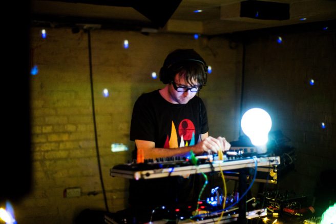
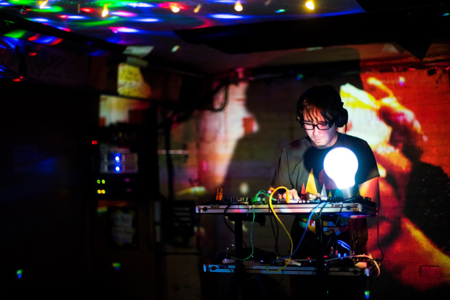
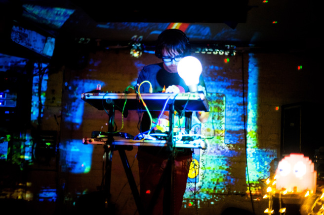
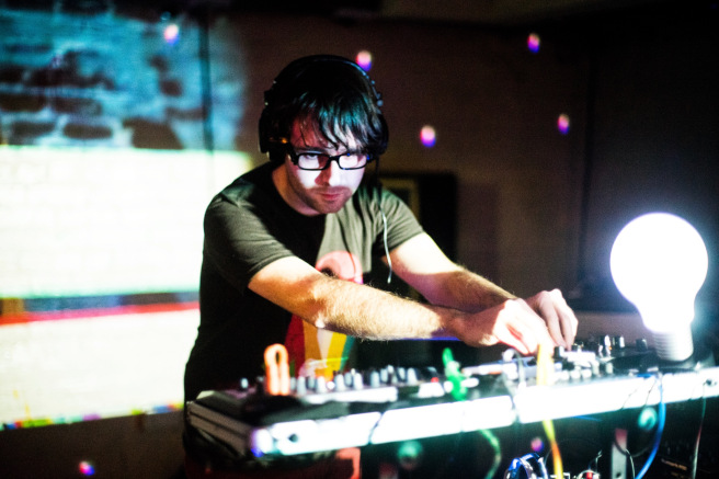
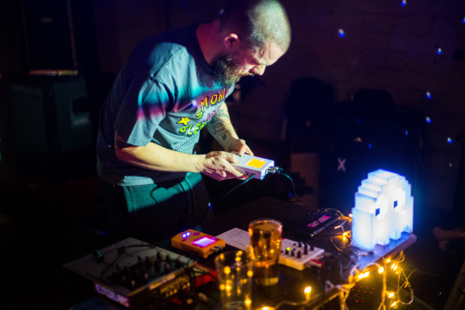
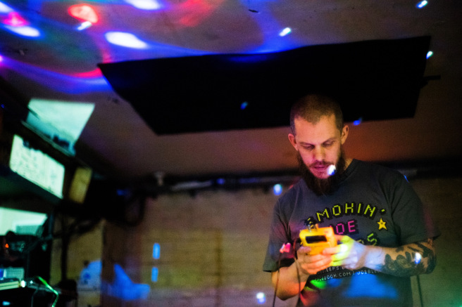
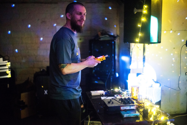
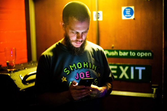
Last night I put on a chip gig in Glasgow, and had some rather wonderful fellow musicians play: Joe Bleeps, Galaxy Wolf, King Keytan, and Myths and Monsters.
Here’s some pictures from the event:


Last night I put on a chip gig in Glasgow, and had some rather wonderful fellow musicians play: Joe Bleeps, Galaxy Wolf, King Keytan, and Myths and Monsters.
Here’s some pictures from the event:
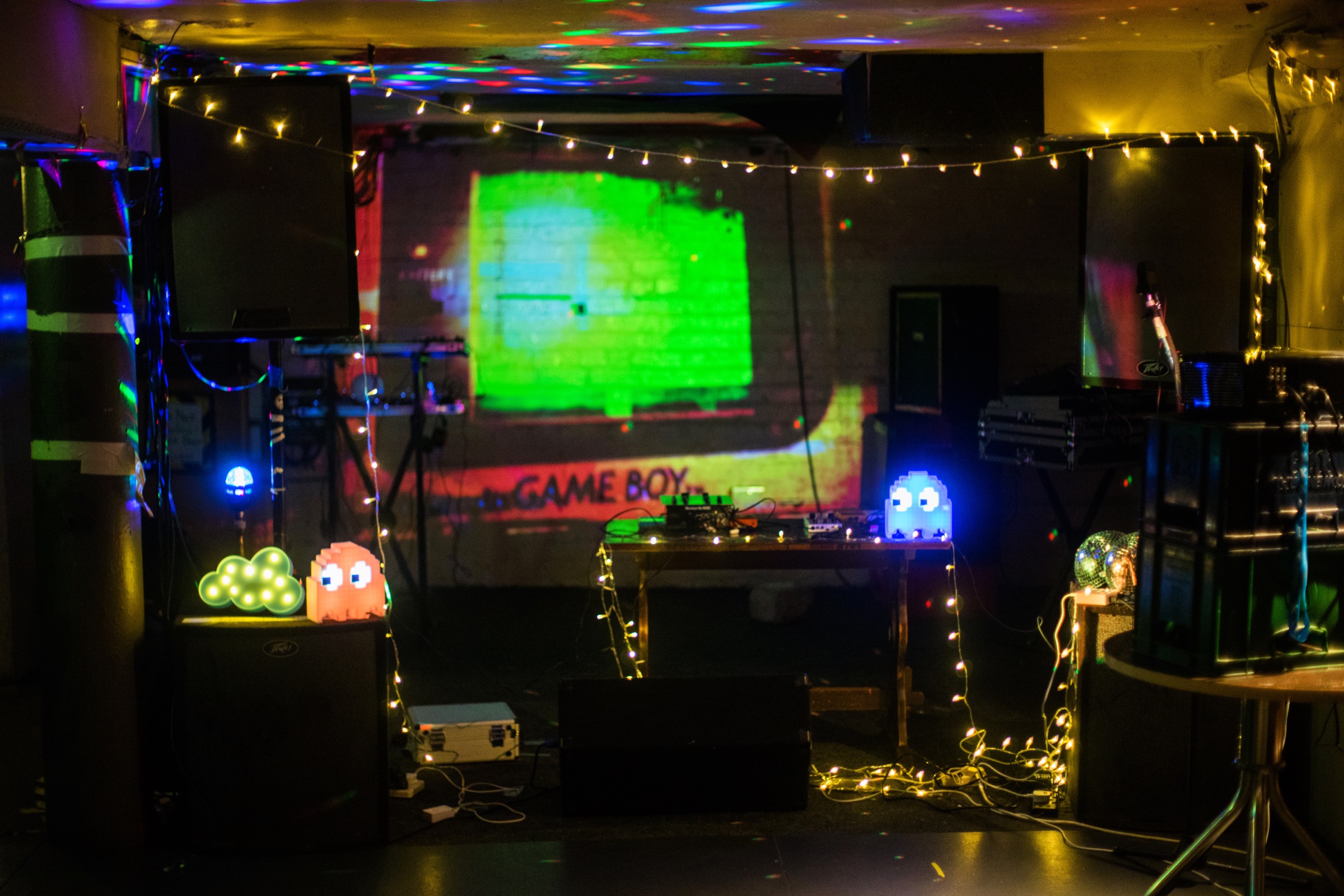
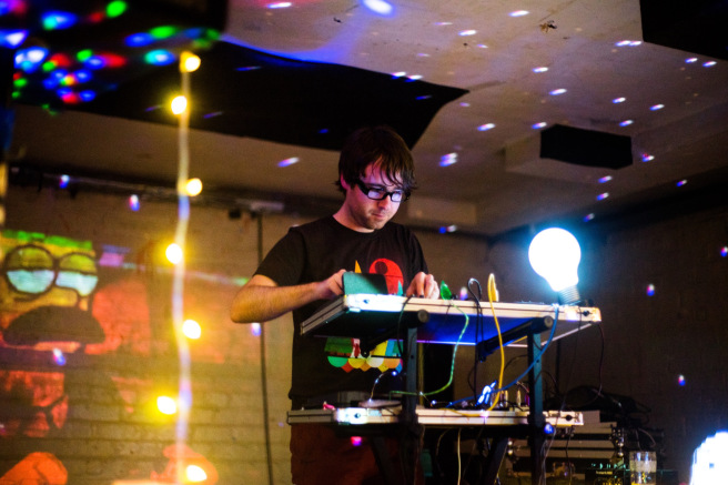
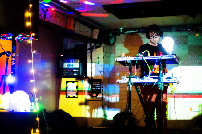
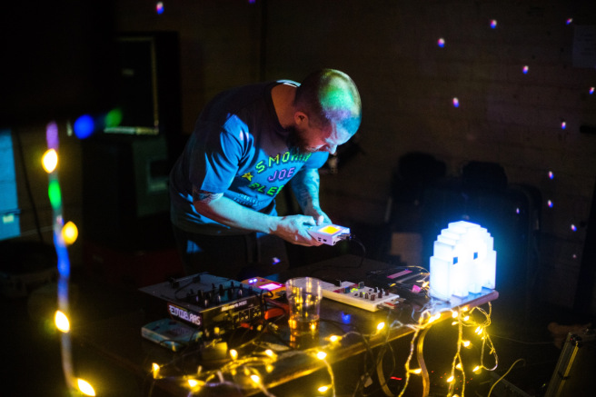
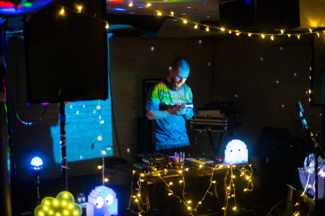
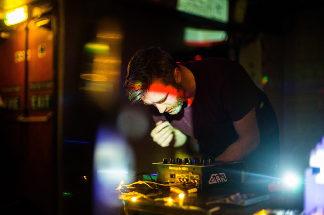
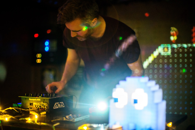
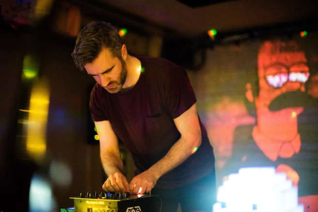
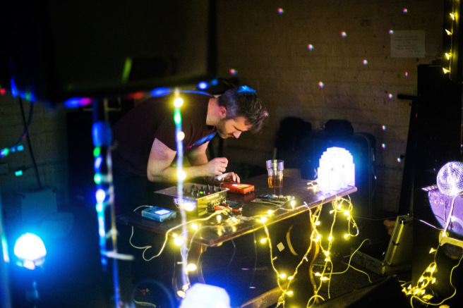
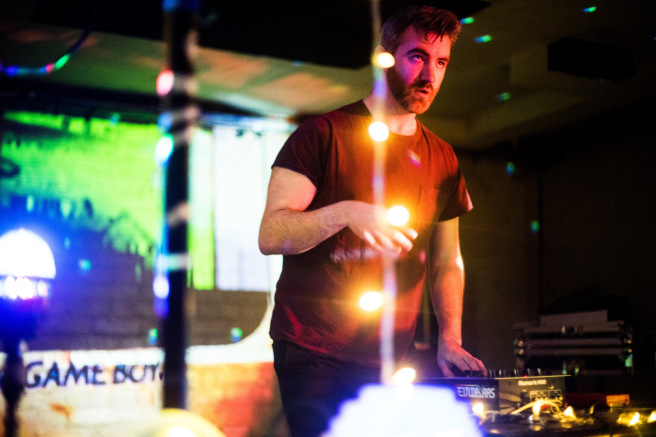
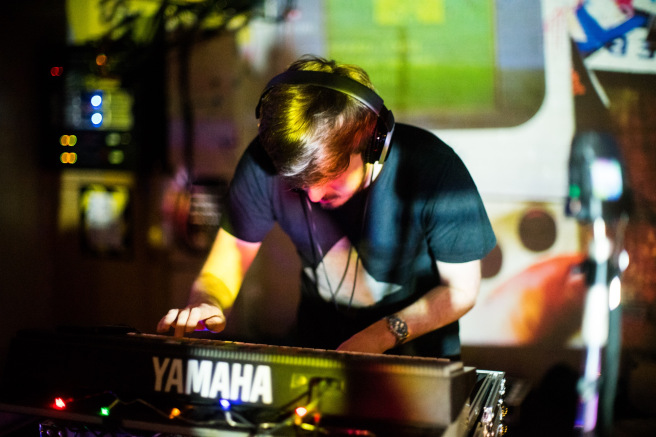
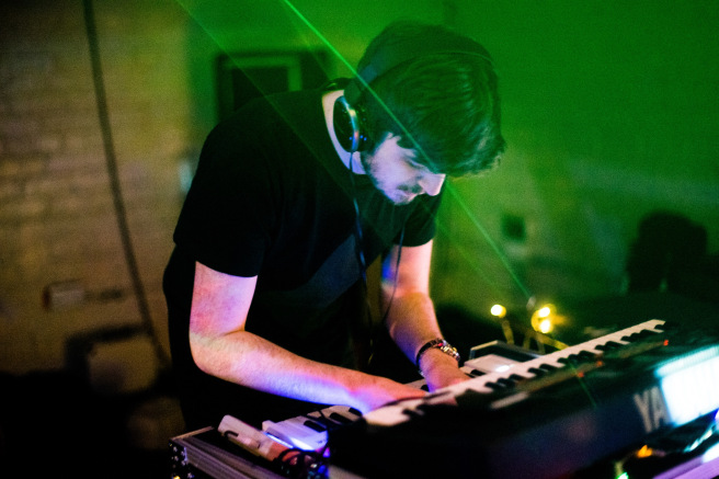
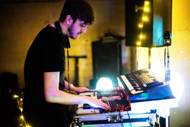
Last night I played as unexpected bowtie at Stereo in Glasgow, closing out the charity gig that I mentioned in the last post.
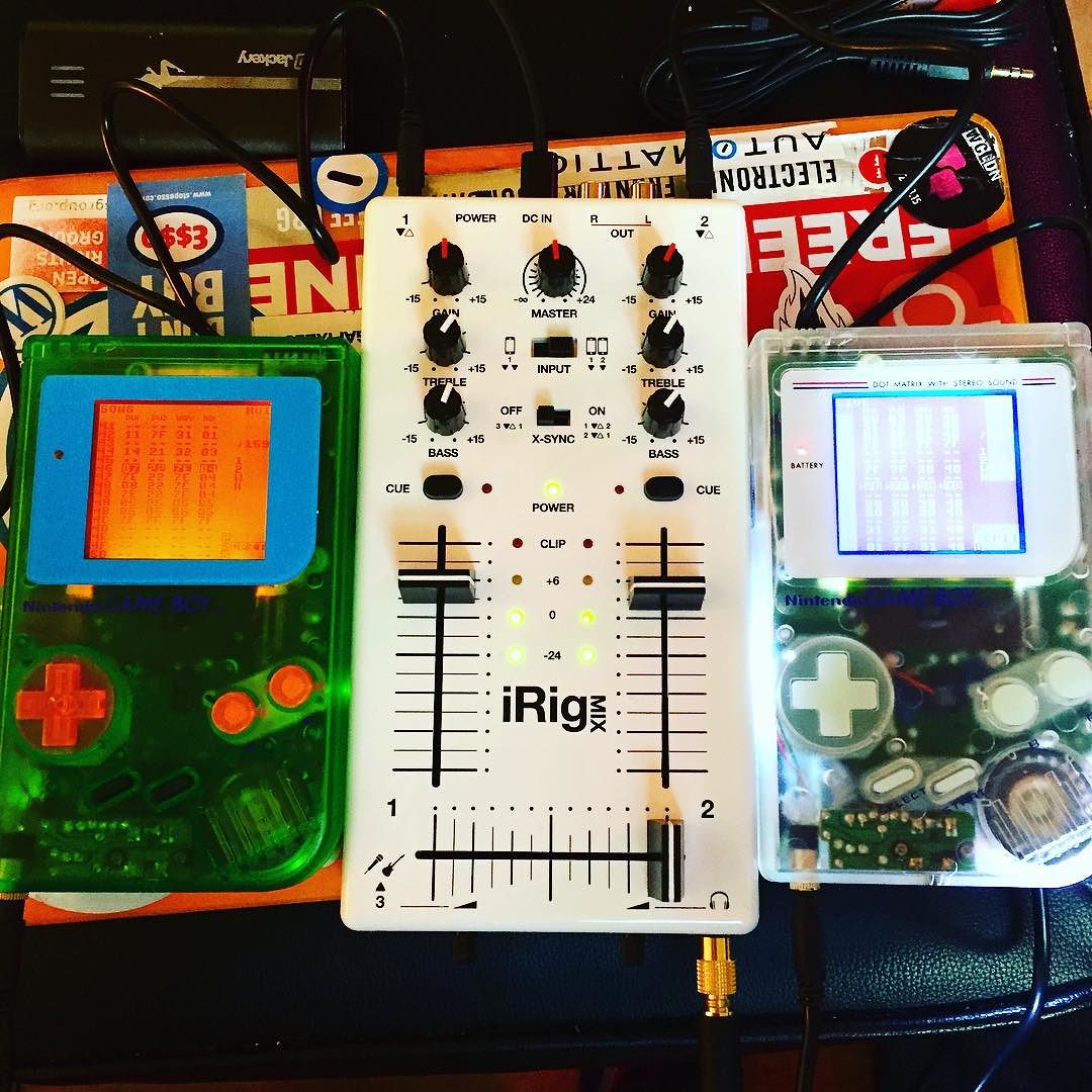
After years of recording in the studio, 2016 has been the year for getting out and playing live - first in Osaka, and now in my home city. This time around, I expanded my setup slightly from having just two Game Boys, to make things a bit more interesting.
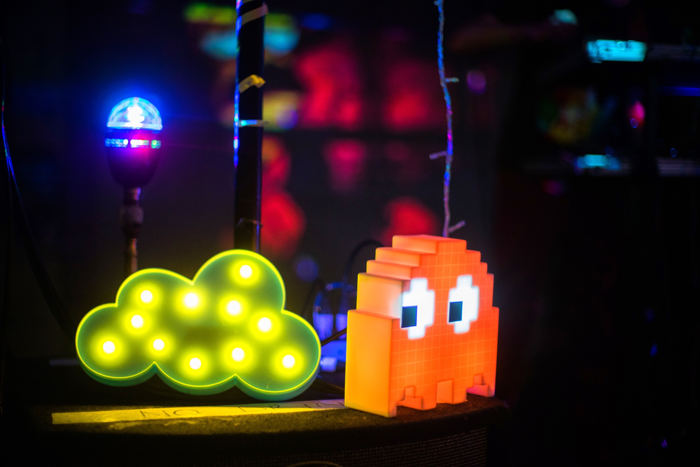
I also roped in Lee aka radiomoths to come along and lend a hand by controlling visuals to spice things up. When the screen broke, he managed to grab some pictures as well. How multi-talented. All pictures from here out are thanks to him…
Thanks a lot to the Uncovered Artistry folks for having us!
Check out the video below for a look at a bit of the gig…
I’m going to be in Japan in the next couple of weeks, and have confirmed my first live outing as unexpected bowtie, at Space Station in Osaka, which is apparently in the ‘Top 30 Recommended Sights of Japan as Chosen by Foreign Visitors‘. The set will be stripped down to a single Game Boy only, given that we are travelling, so should be something a little different. If you happen to be in the area, it’d be awesome to see you there!
To mark the occasion, I’ve written a new track that’s up now on Soundcloud. Composition wise, it’s just a single Game Boy, with a tiny little added bit of Commodore 64, and extra drums. Enjoy!
Over the past couple of months I’ve been acquiring different bits of gear in a sort of obsessive kleptomaniac fashion to build upon the basic foundations of chiptune, and explore the different things I can do with it. As part of that, I’ve gotten a bunch of cool (and definitely not cheap) hardware sequencers… but I find myself constantly coming back to the Game Boy.
Musicians in the chiptune world often talk about the limitations of the console as one of the things that inspires them. For me, it’s probably the opposite: I am amazed at just how powerful these old handhelds can be, controlling all sorts of different gear. Primarily though, I just love composing on LSDJ.
The natural progression from drouth feels like it lies in an album that still has its roots firmly in the chipmusic world (composed entirely on a Game Boy - with the DMG sounds in the mix) - but with a deeper electronic influence, with the handheld sequencing other synthesisers to a greater degree.
I visited Montreal recently, and composed a track on the plane rather than watching the same old terrible TV re-runs that were available (another plus for the Game Boy there in its portability…). When I got back to Glasgow, I put it all together and recorded it. Have a listen below:
It’s been a while since I got pished on a Saturday night and just recorded some music. Well, I ended up recording after an hour of fighting with my mixer to work out why the stereo output was only producing mono…
There’s always the risk that it could have been my crappy soldering, which meant testing out every possible step. So many variables. Surprisingly, it wasn’t actually any of the Gameboys, but the mixer.
I’m pretty pleased with the result, and it should give a hint as to what the next album will sound like. Listen to and download it below:
To finish off, here’s a picture of my tidied up workspace.
Once you get over the steep initial learning curve of learning how to use a tracker like LSDJ on the Gameboy to make music, they can be a real pleasure to use: both powerful and simple.
Whilst the sounds you get out of the old Nintendo handhelds are amazing, there comes a point where you feel like you’ve gotten all you can out of them for the track that you’re working on, and at that point start to look into layer sounds from different places. There are a ton of different electronic synths and samplers out there, but I’ve never been a big fan of writing loops on them; the process often seeming unintuitive and overly complicated. It would be far easier to be able to program them using the familiar LSDJ layout, but that seemed impossible.
As I recently discovered, it apparently isn’t impossible at all. Back in 2011 I bought a special DIY-built MIDI device called an ‘Arduinoboy‘ from a guy called Ralph Tyler (aka NeX), who is a bit of a legend in the Gameboy modification world. This clever wee box brings MIDI connectivity to the handheld, and I have always used it up till now to play the Gameboy as if it was a synth, using a bog standard keyboard (the musical kind) and an app called mgb to trigger the notes. Pretty cool, but it turns out that LSDJ can now be used to send MIDI notes as well. I stumbled upon a video from chip musician jefftheworld doing just that, with a bunch of different Korg Volas, and it sounded just wonderful.
Just watch this… Skip to 1 minute to see the Gameboy kick in.
I decided I had to give this a go, so got my hands on a Korg Volca Bass, which is a really cool wee beast. I already had the Arduinoboy, so figured it shouldn’t be all that difficult to get up and running.
I should have known better.
I connected everything up, and LSDJ was sending clock signals successfully from the Gameboy to the Volca, but it wasn’t sending the notes themselves. Hmm. After a bit of research on chipmusic.org, I realised that the LSDJ ROM I had loaded onto my EMS Flash Cart (a specially made Gameboy cartridge that lets you load ROMS on via USB) wasn’t the right version, and so didn’t support the MIDIOUT mode. Not a big deal, as once you pay for one version of LSDJ, you get access to them all. I fired up the EMS Flasher Utility for Mac in the Terminal, and loaded the new one over.
Everything connected up again; LSDJ set to MIDIOUT mode; and the notes added in via the newly available ‘Q’ commands (Q00) on the existing track I had loaded up to test things out… I hit play, and… nothing. After a bit more research, I discovered that because I had bought my Arduinoboy years ago, the software that it was running was also probably out of date, and didn’t include the support for LSDJ’s MIDIOUT mode.
I’d never updated an Arduino board’s software before, and never even seen inside the Arduinoboy as I hadn’t built it… but, I’m no stranger to computers, and it seemed that updating the ‘sketch’ as it’s called would be as simple as opening up the case, and then connecting up the Mac to the Arduino’s onboard mini USB. That in mind, I grabbed a hold of my Tri-wing screwdriver (particular to Nintendo), and carefully began to open up the Arduinoboy.
I forgot to mention, the Arduinoboy is neatly nestled inside an old four player adapter device, with the MIDI ports on the sides. Pretty cool.
I got the case opened up, and discovered my worst fear. The Arduino board that was acting as the brains of the operation was a ‘Mini Pro’, which meant that it had no USB built in, requiring a ‘breakout’ board, or some other connection to load the software on.
Crap.
By the looks of things, this meant de-soldering a lot of the existing connections that Ralph had put in there, and I really really didn’t want to do that, as his work with a soldering iron would always be infinitely better than mine… since uh, he knows wtf he’s doing. However, I couldn’t see any other way around it,so dropped him an e-mail whilst I looked up some schematics online. I had a spare Arduino Uno board lying around that I could potentially use to load the software on, so all was not lost yet - it would just be a bit more complicated than expected (shock).
It turns out that Ralph is extremely nice, and with his encouragement I started to solder the various jump wires from the Uno board to the Micro Pro based on the steps here. The schematics in the comments were particularly helpful.
There are various glaring errors in the above image. Firstly, I took out the header pins to solder the wires as it seemed easier to do flat, but didn’t check whether or not the pins would all be next to each other. It won’t surprise you to learn that they are not - so there were a couple of extra stragglers. Secondly, I used wire that was far far too thick, because stripping down the thin wire is more of a pain. As it turns out, trying to solder that stuff to a tiny Mini Pro board is not going to happen, so I had to join all of the strands of big wire to smaller wire afterwards. Sigh.
Anyway, after a while I got all of the wires in place (give or take), and was ready to connect it up to the laptop and flash the software. Woohoo!
But, of course that wasn’t the end of the story. It turns out that the Arduino Uno board I got isn’t actually an official one, but a cheap knock off. I knew this at the time of purchase of course, and was trying to be a cheap bastard. However, it then came back to bite me as the Arduino IDE software kept coming back repeating the same error - something about stk500_getsync() and how the board couldn’t be found. Even after installing the pokey third party drivers it didn’t seem to be working.
I went down a rabbit warren of Google searches, checking the verbose logging in the console for errors and getting led on a wild goose chase by problems that were nothing to do with my own, and before long I felt like I was hallucinating. I was about to send a furious e-mail to the eBay seller that had sold me the Arduino ripoff in the first place, when I tried to load the Arduinoboy software onto it - without the Arduino Mini Pro connected. That worked, which meant that the board itself wasn’t the problem - but something to do with the communication between the two boards. Interesting.
That didn’t mean things were solved soon after though, as the problems still remained, and there was no obvious answer. I had checked and re-checked the connections to the board so many times I could hardly see them any more when I squinted, and was getting more and more frustrated. I thought I might have accidentally short circuited something or trashed the board by over-heating it… Things weren’t looking good.
After ages I finally stumbled upon a different set of instructions. To sum things up, there are two different kinds of chip installed on these Arduino boards: the classic ‘DIP’ kind (which looks kind of like a digital cockroach), and the more modern ‘SDM’. The former can be easily removed; the latter cannot. Either way, they need to be bypassed on the host somehow - or else the Arduino programmer gets confused between the two boards and freaks out. It’s just that it’s easier to do with DIP chips than SDM. (Guess which kind I have?). There are all sorts of conflicting ideas about how to do this effectively with SDM chips on the web, but as it turns out, the easiest way is to upload a particular sketch to the Uno board. The Instructables article had a copy of this, and I’m re-uploading it here for posterity: serial-disable.ino.
Some other important things that I learned:
The order I wired up things in the end was:
TX - TX
RX - RX
RESET - RST
GND - GND
5V - VCC
I can’t tell you how relieved I was to see this message:
HALLELUJAH.
So began the task of putting everything back together. I’ve never had the steadiest of hands, and I’m in the middle of Dry January - so have the jakey shakes due to lack of alcohol consumption - so probably not the best time to attempt re-wiring some fiddly electronics that were originally put together by far more deft hands than mine. However, I got it all back in place eventually - hopefully the joins hold out! I do not want to take this thing apart again.
At first my heart sunk, as it didn’t seem like anything had changed. The LED behaviour was a bit weird (less active than before…), and the Gameboy was still just sending clock signals, not notes. AGHH.
After a bit of jiggery pokery, it all came to life though. I was shocked. The damn thing was working.
I’m still not convinced that the LEDs on the Arduinoboy are going in the same pattern that they used to, but since everything seems to be working I’m going to put it down to the software change and think nothing more of it.
I shot a quick video to show the setup in action:
The sound is coming from both the Gameboy and the Volca simultaneously, and I’m using that particular Gameboy as it’s one of the few that still has the internal speaker intact (i.e. not ripped out for some other kind of mod). I fanny about a bit with the Volca controls to show how you can manipulate the sound, but I have no idea what I’m doing with it yet really.
Explanation of steps: You need to set LSDJ to MIDIOUT Sync mode, stick the Arduinoboy on the correct mode (for me it’s whatever the second LED means), and make sure the Volca is set to the right MIDI channel. The first column of LSDJ corresponds to channel 1, and so on. Hold down Write as you power up the Volca to change the channel.
And that, was tonight’s misadventure. I’ve no idea if I’m learning anything by doing all of this stuff or not.