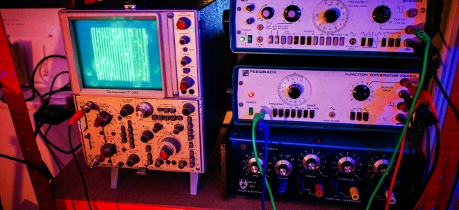
Recently I embarked on an experimentation with old audio test equipment, Specifcally, these devices used in labs and by engineers to diagnose problems with amplifiers, radios, and telephone lines. Err, I think. To be honest, I’m not entirely sure what they were designed for, as I was no good at physics.
Either way, they look cool, and I’ve been interested in exploring some of the possibilities for a while, but didn’t know where to begin. However, I came across this guy called Hainbach on YouTube, who has put together an awesome guide that helped give me the push to dive in. I picked up a few different pieces for cheap on eBay, and began playing about with them to see what I could do. I mostly got a hold of audio signal generators, which are essentially what gives synthesizers their voice. The extent to which you can control them differs from instruments, but I was able to get some amazing sounds out of them.
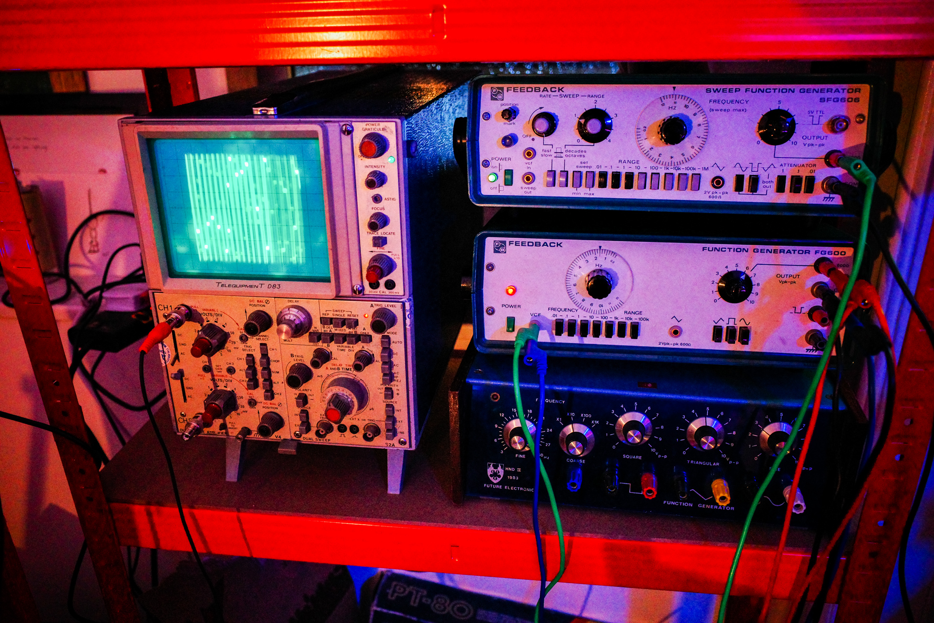
I put together the track below with a single one of these devices, controlled by my Eurorack to some extent. Unlike a lot of my other music, there’s very few effects on here, and very few layers; the sounds of the test equipment stand on their own. Pretty much everything you hear (minus drums) is from the Feedback Function Generator. I love that I can get a really incredible ratchety bass sound out of this, jumping down from nice and melodic to aggressive. Perhaps I’m imagining it, but I haven’t been able to get that kind of usable range from any of my other equipment. Either way, there’s something deeply satisfying about making music with aging bits of technology that were never intended to be used this way - it sparks the creative process in a different way.
At some point I’ll go through and write a bit more about this stuff in detail, but for now, I put together this video with my initial faffing about:
I’m the sort of person who is far more comfortable in dark spaces than I am with bright, overhead lights. I also love how colourful lights look in pictures, so am always on the hunt for different ways to implement LEDs. They also go hand in hand with a sweeeeet looking music setup.
Anyway, I used to have a neon sign in the home studio which gave a real nice ambience, but unfortunately it blew up… so I had to hunt for a replacement. I trialled some 5v RB LED strips on the outside of the case, and it looked pretty cool - but it needed some tweaking.
I came across the Doepfer A-197-3 module which allows you to control LEDs with CV signals from the Eurorack, and it got me thinking. I didn’t want to spend the money or HP on the Doepfer without first figuring out if it would be worth it. It worked with 12v LED strips, so I picked up 5m of them off of eBay, complete with what claimed to be a ‘sound reactive controller’. In theory, it should play along nicely with the audio output from my rig, though to be honest, I wasn’t holding out much hope. These kinds of thing are infamously of questionable quality, and I fully expected to have to pick up the Doepfer module anyway.
However… it actually turned out alright. The modes and sensitivity controls work quite nicely, and despite a few hiccups, putting the strips together was easier than I expected. I ended up lighting the outside of the three main parts of my setup, and it looks pretty great. I put together a video below going into some more detail, and showing them in action. Take a look below if you’re interested.
This isn’t going to be the end of the lighting adventures though. I have a few ideas up my sleeve that I am going to try out over the next wee while, so watch this space (and maybe subscribe to the YouTube).
Last night I played as unexpected bowtie at Stereo in Glasgow, closing out the charity gig that I mentioned in the last post.
After years of recording in the studio, 2016 has been the year for getting out and playing live - first in Osaka, and now in my home city. This time around, I expanded my setup slightly from having just two Game Boys, to make things a bit more interesting.
I also roped in Lee aka radiomoths to come along and lend a hand by controlling visuals to spice things up. When the screen broke, he managed to grab some pictures as well. How multi-talented. All pictures from here out are thanks to him…
Processed with VSCOcam with c3 preset
" data-medium-file="https://unexpectedbowtie.files.wordpress.com/2016/01/img_8849.jpg?w=300" data-large-file="https://unexpectedbowtie.files.wordpress.com/2016/01/img_8849.jpg?w=656"/>
Once you get over the steep initial learning curve of learning how to use a tracker like LSDJ on the Gameboy to make music, they can be a real pleasure to use: both powerful and simple.
Whilst the sounds you get out of the old Nintendo handhelds are amazing, there comes a point where you feel like you’ve gotten all you can out of them for the track that you’re working on, and at that point start to look into layer sounds from different places. There are a ton of different electronic synths and samplers out there, but I’ve never been a big fan of writing loops on them; the process often seeming unintuitive and overly complicated. It would be far easier to be able to program them using the familiar LSDJ layout, but that seemed impossible.
As I recently discovered, it apparently isn’t impossible at all. Back in 2011 I bought a special DIY-built MIDI device called an ‘Arduinoboy‘ from a guy called Ralph Tyler (aka NeX), who is a bit of a legend in the Gameboy modification world. This clever wee box brings MIDI connectivity to the handheld, and I have always used it up till now to play the Gameboy as if it was a synth, using a bog standard keyboard (the musical kind) and an app called mgb to trigger the notes. Pretty cool, but it turns out that LSDJ can now be used to send MIDI notes as well. I stumbled upon a video from chip musician jefftheworld doing just that, with a bunch of different Korg Volas, and it sounded just wonderful.
Just watch this… Skip to 1 minute to see the Gameboy kick in.
I decided I had to give this a go, so got my hands on a Korg Volca Bass, which is a really cool wee beast. I already had the Arduinoboy, so figured it shouldn’t be all that difficult to get up and running.
I should have known better.
I connected everything up, and LSDJ was sending clock signals successfully from the Gameboy to the Volca, but it wasn’t sending the notes themselves. Hmm. After a bit of research on chipmusic.org, I realised that the LSDJ ROM I had loaded onto my EMS Flash Cart (a specially made Gameboy cartridge that lets you load ROMS on via USB) wasn’t the right version, and so didn’t support the MIDIOUT mode. Not a big deal, as once you pay for one version of LSDJ, you get access to them all. I fired up the EMS Flasher Utility for Mac in the Terminal, and loaded the new one over.
Everything connected up again; LSDJ set to MIDIOUT mode; and the notes added in via the newly available ‘Q’ commands (Q00) on the existing track I had loaded up to test things out… I hit play, and… nothing. After a bit more research, I discovered that because I had bought my Arduinoboy years ago, the software that it was running was also probably out of date, and didn’t include the support for LSDJ’s MIDIOUT mode.
I’d never updated an Arduino board’s software before, and never even seen inside the Arduinoboy as I hadn’t built it… but, I’m no stranger to computers, and it seemed that updating the ‘sketch’ as it’s called would be as simple as opening up the case, and then connecting up the Mac to the Arduino’s onboard mini USB. That in mind, I grabbed a hold of my Tri-wing screwdriver (particular to Nintendo), and carefully began to open up the Arduinoboy.
I forgot to mention, the Arduinoboy is neatly nestled inside an old four player adapter device, with the MIDI ports on the sides. Pretty cool.
I got the case opened up, and discovered my worst fear. The Arduino board that was acting as the brains of the operation was a ‘Mini Pro’, which meant that it had no USB built in, requiring a ‘breakout’ board, or some other connection to load the software on.
Crap.
By the looks of things, this meant de-soldering a lot of the existing connections that Ralph had put in there, and I really really didn’t want to do that, as his work with a soldering iron would always be infinitely better than mine… since uh, he knows wtf he’s doing. However, I couldn’t see any other way around it,so dropped him an e-mail whilst I looked up some schematics online. I had a spare Arduino Uno board lying around that I could potentially use to load the software on, so all was not lost yet - it would just be a bit more complicated than expected (shock).
It turns out that Ralph is extremely nice, and with his encouragement I started to solder the various jump wires from the Uno board to the Micro Pro based on the steps here. The schematics in the comments were particularly helpful.
There are various glaring errors in the above image. Firstly, I took out the header pins to solder the wires as it seemed easier to do flat, but didn’t check whether or not the pins would all be next to each other. It won’t surprise you to learn that they are not - so there were a couple of extra stragglers. Secondly, I used wire that was far far too thick, because stripping down the thin wire is more of a pain. As it turns out, trying to solder that stuff to a tiny Mini Pro board is not going to happen, so I had to join all of the strands of big wire to smaller wire afterwards. Sigh.
Anyway, after a while I got all of the wires in place (give or take), and was ready to connect it up to the laptop and flash the software. Woohoo!
But, of course that wasn’t the end of the story. It turns out that the Arduino Uno board I got isn’t actually an official one, but a cheap knock off. I knew this at the time of purchase of course, and was trying to be a cheap bastard. However, it then came back to bite me as the Arduino IDE software kept coming back repeating the same error - something about stk500_getsync() and how the board couldn’t be found. Even after installing the pokey third party drivers it didn’t seem to be working.
I went down a rabbit warren of Google searches, checking the verbose logging in the console for errors and getting led on a wild goose chase by problems that were nothing to do with my own, and before long I felt like I was hallucinating. I was about to send a furious e-mail to the eBay seller that had sold me the Arduino ripoff in the first place, when I tried to load the Arduinoboy software onto it - without the Arduino Mini Pro connected. That worked, which meant that the board itself wasn’t the problem - but something to do with the communication between the two boards. Interesting.
That didn’t mean things were solved soon after though, as the problems still remained, and there was no obvious answer. I had checked and re-checked the connections to the board so many times I could hardly see them any more when I squinted, and was getting more and more frustrated. I thought I might have accidentally short circuited something or trashed the board by over-heating it… Things weren’t looking good.
After ages I finally stumbled upon a different set of instructions. To sum things up, there are two different kinds of chip installed on these Arduino boards: the classic ‘DIP’ kind (which looks kind of like a digital cockroach), and the more modern ‘SDM’. The former can be easily removed; the latter cannot. Either way, they need to be bypassed on the host somehow - or else the Arduino programmer gets confused between the two boards and freaks out. It’s just that it’s easier to do with DIP chips than SDM. (Guess which kind I have?). There are all sorts of conflicting ideas about how to do this effectively with SDM chips on the web, but as it turns out, the easiest way is to upload a particular sketch to the Uno board. The Instructables article had a copy of this, and I’m re-uploading it here for posterity: serial-disable.ino.
Some other important things that I learned:
Crappy knockoff Arduino boards can be good, but also require more fannying about. You need to install special drivers rather than it just work out of the box. Everything is more complex and fills you with needless uncertainty and dread when things go wrong. Just spend some more cash and buy a bloody real one.
The ‘programmer’ choice in the Arduino IDE doesn’t make a difference for most purposes.
You need to make sure that all of the connections to the TX and RX points are removed (except the ones you’ve added from the host Uno board obviously), otherwise it will lock up the board and prevent you from uploading (thanks Ralph!). This meant more de-soldering and trying to remember where to put things back later. *bites nails*.
There was a whole host of talk online about how if you were using a ripoff Arduino host board you would have to hit the reset button manually on the Mini Pro at just the right time to get it to initialise properly and take the software properly, because the reset points on them weren’t there. As it turns out, you don’t need to do that at all; the reset point is just named slightly differently depending on the board you have - and it’s just a matter of finding out what that is and connecting it correctly.
You need to select ‘Pro Mini’ as the target board, as it helps bypass the host board’s chip. Or something.
There are some truly insane people out there giving some really bad and incorrect information about this.
The order I wired up things in the end was:
TX - TX RX - RX RESET - RST GND - GND 5V - VCC
I can’t tell you how relieved I was to see this message:
HALLELUJAH.
So began the task of putting everything back together. I’ve never had the steadiest of hands, and I’m in the middle of Dry January - so have the jakey shakes due to lack of alcohol consumption - so probably not the best time to attempt re-wiring some fiddly electronics that were originally put together by far more deft hands than mine. However, I got it all back in place eventually - hopefully the joins hold out! I do not want to take this thing apart again.
At first my heart sunk, as it didn’t seem like anything had changed. The LED behaviour was a bit weird (less active than before…), and the Gameboy was still just sending clock signals, not notes. AGHH.
After a bit of jiggery pokery, it all came to life though. I was shocked. The damn thing was working.
I’m still not convinced that the LEDs on the Arduinoboy are going in the same pattern that they used to, but since everything seems to be working I’m going to put it down to the software change and think nothing more of it.
I shot a quick video to show the setup in action:
The sound is coming from both the Gameboy and the Volca simultaneously, and I’m using that particular Gameboy as it’s one of the few that still has the internal speaker intact (i.e. not ripped out for some other kind of mod). I fanny about a bit with the Volca controls to show how you can manipulate the sound, but I have no idea what I’m doing with it yet really.
Explanation of steps: You need to set LSDJ to MIDIOUT Sync mode, stick the Arduinoboy on the correct mode (for me it’s whatever the second LED means), and make sure the Volca is set to the right MIDI channel. The first column of LSDJ corresponds to channel 1, and so on. Hold down Write as you power up the Volca to change the channel.
And that, was tonight’s misadventure. I’ve no idea if I’m learning anything by doing all of this stuff or not.
The Mayor of London is something of an anachronism, both charming and disturbing all at once.
The infamously bumbling Mayor of London has rugby tackled children, sought to deploy water cannons and then volunteered to be sprayed by one when their use was banned, and single handedly cleaned up the streets of the British capital with his brush the day after the riots.